

Visual Instruments
Flap Position Indicator
Flap Position Indicator
Couldn't load pickup availability
The Visual Instruments Flap Position Indicator was developed because of frustrations and difficulties we had in maintaining the original flap indicators installed on older Cessna aircraft.
This older style indicator system, evolved from adapted automobile fuel gauge technology used in the 1950’s and 1960’s. It has long been very problematic for many aircraft owners. Some owners simply fly with the indicator inoperative, rather than suffer from never ending repair costs.
Here are some of the reasons these older style Cessna flap indicators fail, and the problems associated with them. We also explain how we have addressed each of these issues with the modern design of the Visual Instruments system.
Share


Documents
Supplemental Type Certificate (STC)
Approved Model List (AML)
Installation Instructions
Benefits
Electrolytic Corrosion
The Cessna system employed a sending unit that was not hermetically sealed, causing the electrical wire windings of the rheostat to become corroded. This happens especially fast if you keep your aircraft in a wet climate. The corrosion is accelerated by Electrolyses, as the windings are electrically energized whenever the master is turned on.
The Visual Instruments Indicator employs a high quality sealed potentiometer in its sender. The potentiometer is rated to 40,000 ft. It uses low-level electronic signals to communicate with the display, so the higher currents employed by the older style gauges are not necessary.
Transmitter Coupling
The Cessna unit uses a thin wire rod to connect the sender transmitter to the flap pulley. This wire is easily bent and is difficult to adjust. It is the source of many reading errors.
The Visual Instruments Indicator Design is quite clever. It uses a solid aluminum follower arm, which is connected to the flap pulley. The arm is allowed to rotate on the shaft of the potentiometer making the adjustment process simple. Three screws are tightened to secure the position permanently.
Price of Cessna Factory Replacement System as Compared to Visual Instruments Flap Position Indicator System?
Cessna’s flap position indicator systems were made by AC Spark and then by Stewart-Warner until these companies went out of business several decades ago. Since then these systems have been made by Rochester Instrument Co. THE ORIGINAL GAUGES AND SENDER UNITS MADE BY AC SPARK & STEWART-WARNER ARE NOT COMPATIBLE WITH THE ROCHESTER GAUGES AND SENDER UNITS. THUS, IF YOU OWN ONE OF THESE OLDER COMPONENTS AND IT GOES OUT, YOU THEN HAVE TO PURCHASE BOTH THE FLAP INDICATOR DISPLAY GUAGE AND THE SENDING UNIT AT A SALES PRICE FROM CESSNA OF APPROXIMATELY $1,800.00, AND CURRENTLY THERE HAS BEEN A 12-WEEK TO 6- MONTHS WAIT TIME.
The good news is that you can purchase the Visual Instruments Flap Position Indicator System for less than the factory replacement system, it will have a 1-year warranty (much longer than Cessna’s warranty), our system is much more modern with an LED light bar graph & self-dimming capabilities.
Sinusoidal and Low-Resolution Readings
The Cessna gauge is not linear. (The readings at ends of the scale are bunched up.) This is because the sender is connected to the rotating flap pulley, which moves in a sinusoidal motion.
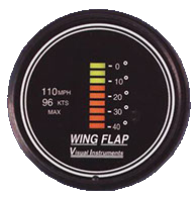
The Visual Instruments Indicator corrects for this error in its electronic circuits. Flap position is displayed on a linear bar graph. The Display has a much higher resolution (5-degrees) for each bar as opposed to 10-degree markings on the Cessna indicator. It is very similar to the way commercial jets display their flap position on their Glass Cockpit Displays.
Difficulty in Reading the Indicator, Especially at Night
On many model Cessna’s the flap indicator is located way off on the right side of the instrument panel. This creates parallax errors and difficulties reading the indicator. At night, the gauge is not internally lit, making readings even more difficult.
Because of its LED display, the Visual Instruments Indicator is not subject to parallax errors. It has an incredibly wide viewing angle so the pilot will have no trouble reading it in the daylight or at night. Its color-coded display makes it easy to identify the 10-degree position for an emergency go-around procedure. The Indicator is equipped with an internal light sensor that adjusts the display to the proper brightness automatically.
Frequently Asked Questions (FAQs)
Who can install the Visual Instrument Flap Position Indicator?
Any A&P mechanic or repair station can install this indicator in your aircraft.
An IA will need to sign FAA Form 337 and submit it to the local FSDO.
How long does it take to install the Visual Instrument Flap Position Indicator?
Installation takes about 2 hours.
I received notice of Cessna service letter SEB00-9. Does the Visual Instruments system accomplish the same?
Yes. The Visual Instruments flap position indicator replaces A.C. Spark Plug, Stewart Warner, or Rochester systems with an easier to read display at a lower cost.
Why can I not label my old indicator “inoperative” and look over my shoulder to see what position my flaps are in?
While 14 CFR Part 91.213 allows you to operate an airplane with some inoperative instruments and equipment, the flap position indicator is a required instrument and cannot be labeled “inoperative”.
See: 14 CFR Part 91.213 and CAR 3.353
Will I need any other parts to complete the system?
Our Flap Indicator Kit includes all parts required for installation: the transmitter, display assembly, hardware kit and instructions and STC paperwork.
Are any airframe modifications required to install this system?
No, just remove the old Transmitter and Indicator and replace with the Visual Instruments Transmitter and Display.
Can I replace only the indicator in my airplane?
No. Our indicator is not compatible with any of the Cessna transmitters.
When Cessna introduced the electric flap system, the first indicators were manufactured by A.C. Spark Plug. Cessna later (around 1965) switched to an indicating system manufactured by Stewart Warner.
These two systems were not compatible with each other (see Cessna service letter SE70-12 dated May 28 1970) and Cessna recommended replacing both the transmitter and indicator at the same time.
Current replacement parts are manufactured by a third company named Rochester which are also not compatible with the earlier systems (see Cessna service letter SEB00-9 dated Nov 6 2000).
THE COST FOR THESE ANALOG REPLACEMENT PARTS RUNS APROX $1,800.00 FROM CESSNAS AND THE WAIT TIME USUALLY RUNS ANYWHERE FROM 12 WEEKS TO 6 MONTHS.
Where are Visual Instruments Flap Position Indicators manufactured?
Visual Instruments products are MADE IN THE U.S.A. in McMinnville, Oregon.